EXTERNAL WALLS: CAVITY WALL CONSTRUCTION WITH AIRCRETE
In an external cavity wall construction, each leaf has a distinct purpose
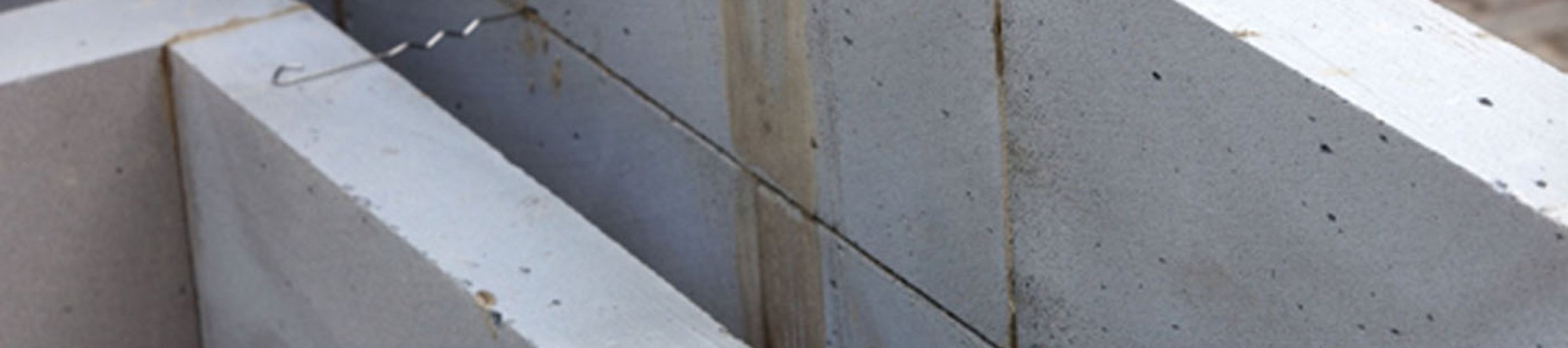
External cavity wall construction with aircrete
Cavity wall construction – where a single wall is constructed of two leaves of masonry with a cavity in between – has been the most common construction method for external walls in residential buildings in the UK since the 1920s.
Each leaf has a distinct purpose. The external leaf protects the structure from moisture penetration while the inner leaf provides the main structural support for the building. Celcon Blocks fulfil both these requirements.
A typical external wall for residential buildings today will comprise an internal, loadbearing leaf of aircrete, a cavity filled or partially filled with insulation and an external leaf of brickwork.
For the loadbearing inner leaf, a range of Celcon Blocks of different strengths are available, with the choice dependent upon the height and design of the building under construction. Wall ties conforming to BS EN 845-1 should be used in cavity wall construction, with a minimum embedment of 50mm into each leaf.
Thermal performance of external cavity wall
Today one of the primary functions of a cavity wall is to provide effective thermal insulation. The focus on producing ever more energy efficient homes has resulted in significant thermal performance requirements for the external wall structure.
With its inherent thermal efficiency, aircrete is an ideal material for constructing external walls. Building Regulations Approved Document L: conservation of fuel and power, (revised in 2021), gives limiting U-Values for each building element. For external walls, the maximum U-Value permissible is 0.26 W/m2K.
This performance can be achieved in a number of ways – varying the width of the cavity and specifying different insulation and wall materials.
H+H has produced a list of the U-Values provided by different cavity wall constructions using its Celcon Blocks. The good news is that it is easily possible to meet the limiting U-Value of current building regulations with a 300mm wall thickness – ie with a 100mm cavity.
The list of wall details illustrates how different combinations of Celcon Blocks, insulation types and cavity widths can produce wall constructions with a U-Value a low as 0.11 W/m2K
Thermal Bridging
As required U-values have been driven down, the significance of heat loss through thermal bridging increases.
Non-repeating thermal bridging at the junction of building elements (floors, walls and roofs) can account for as much as 50% of the fabric only heat loss.
The use of H+H aircrete can significantly reduce the thermal bridge effect at junctions as it will have a far better thermal resistance than denser materials. Where aircrete is used both for separating walls and the inner leaves of external walls, heat losses at thermal bridges can be reduced by around 50%.
Constructing a cavity wall
Cavity walls can generally be built on a strong concrete base on which the cavity wall is constructed centrally.
H+H also produces a foundation block which, at 300 – 355mm wide, is designed specifically to support an external cavity wall.
Typically the two leaves of a cavity wall will be built simultaneously, with care being taken to stop any mortar being dropped into the cavity as this may cause thermal bridges. At the end of each day the top of the cavity must also be protected to make sure no debris falls into the cavity.
The exception to this build method is where Thin-Joint aircrete is being used for the inner leaf. Thin-Joint is much faster to build and, with its quick-setting Thin-Joint mortar, an entire storey-height can be built in a single day.
In Thin-Joint constructions it is common to build the structural internal walls with floors and roof first. This results in a weathertight shell allowing the interior trades to start work while the brick outer leaf is still under construction. The resulting time-saving is significant.
Filling the cavity
Depending on the type of insulation specified, it will either fully fill the cavity or provide a partial fill. In the latter case, the insulation material will be fixed to the external face of the internal leaf of the cavity wall, allowing the remainder of the cavity to be ventilated without significant heat loss.
Where the cavity is fully filled with insulation it is hugely important to make sure that no path is created – for example, by protruding mortar – for the penetration of moisture between the outside and inside.
Any moisture that reaches the cavity from the outside, runs down the internal surface of the external leaf and is directed to weep holes in the outer leaf by cavity trays, where it will drain to the outside. Cavity trays are included where there are penetrations across the cavity, such as doors and windows, and at the bottom of the wall above the damp proof course.
Designing a cavity wall
H+H has produced a series of standard Junction details for cavity walls, both full fill and partial fill standard cavity walls and for Thin-Joint full fill and Thin-Joint partial fill walls.
Increasing thermal performance
The introduction of cavity wall construction significantly improved both the weathertightness and thermal performance of external walls. Further refinements in wall design plus the addition of thermally efficient insulation and aircrete blockwork has driven performance ever higher.
This is starkly illustrated in a comparison of typical U-Values of different wall structures:
- Solid brick wall 2.0 W/m2K
- Cavity wall with no insulation 1.5W/m2K
- Insulated cavity wall with aircrete 0.26W/m2K or less